
Home > Foundation > Linear Position
Linear Position
Position or linear position is the location of a point of interest at a given time instant. It is necessary to use a particular reference frame to describe a position objectively. Figure 1A shows the position vector (arrow) of the body COM at TB described in a 3-dimensional Cartesian (rectangular) coordinate system (OXYZ-system). In this reference frame, the x-axis is aligned with the forward-backward direction while the y-axis with the toward-away direction. The z-axis is aligned vertically upward: upward-downward direction. Position vector is the arrow drawn from the origin of the coordnate system to the location in question: r. The position vector is equal to sum of three vectors defined parallel to the coordinate axes and connected in the tip-to-tail manner: i.e. component vectors. The coordinates (x, y, and z) come from these component vectors. These three coordinates are independent from each other since the axes are perpendicular to each other.
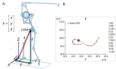
Figure 1. Position vector of the body COM. Vector r can be resolved to three component vectors along the coordinate axes and the position can be described by the x, y, and z coordinates.
Motion of the body COM can be assessed based on the coordinates. For example, Figure 1B shows the motion of the body COM in the frontal plane (YZ-plane). The frontal-plane motion can be divided into four phases: 1) away (BA to MB), 2) upward (MB to EPR), 3) toward and downward (EPR to ED), and 4) toward and upward (ED to MF).
Motion trajectory (path plot) is quite useful in understanding the motion of a point of interest (such as the hand center or clubhead). A trajectory is a line connecting consecutive positions over time. For example, Figure 2 shows the posture at TB of a PGA Tour player and his hand center and clubhead trajectories along with the functional swing plane (FSP) computed from the clubhead trajectory. According to Jim Hardy's classification, his swing is classified as two-plane swing as the shoulder line and lead arm do not align at TB in the down-the-line view. For a two-plane swinger, however, his FSP is quite flat (43°). During the backswing the clubhead goes high up and then starts moving down toward the TB position. This downward motion of clubhead causes an abnormally flat FSP. So it is not ideal to judge the swing style just based on the posture at TB. TB is just a point of a continuous transition motion.
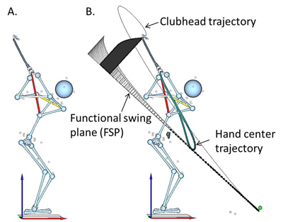
Figure 2. Posture at TB (A) and motion trajectories of the hand center and clubhead (B). B also shows the functional swing plane (FSP).
Relative Position and Displacement
Another basic kinematic concept directly related to position is the relative position of one point to another. The relative position of Point 2 (club's COM in Figure 3) to Position 1 (the hub; mid-trunk point) is simply a straight arrow drawn from Point 1 to Point 2. Relative position essentially shows one point's location relative to another.

Figure 3. Relative position of club's COM to hub. A straight arrow drawn from the hub to club's COM is the relative position vector. The components of the relative position can be obtained by simply subtracting the coordinates of the hub from those of club's COM.
While Figure 3 involves positions of two different points at the same time instant, the relative position of a point at one time instant to another time instant can also be used in the analysis. Figure 4A shows the relative position of pelvis COM to its initial position (![]() ) at EDA. The relative position vector is the straight arrow drawn from the initial position to the position of interest (i.e. EDA). Figure 4B is the relative position plot of pelvis COM including all three components: forward/backward (F/B; red line), toward/away (T/A; green line), and upward/downward (U/D; blue line). The F/D motion reveals three distinct phases: 1) forward (BA to EPR), 2) backward (EPR to EDA), and 3) forward again (EDA to MF). The F/B motion of pelvis COM is associated with rotation of the pelvis. Both the T/A and U/D motions are characterized by two phases: away (BA to midway to MB) followed by toward (thereafter) and downward (BA to EDA) followed by upward (EDA to MF).
) at EDA. The relative position vector is the straight arrow drawn from the initial position to the position of interest (i.e. EDA). Figure 4B is the relative position plot of pelvis COM including all three components: forward/backward (F/B; red line), toward/away (T/A; green line), and upward/downward (U/D; blue line). The F/D motion reveals three distinct phases: 1) forward (BA to EPR), 2) backward (EPR to EDA), and 3) forward again (EDA to MF). The F/B motion of pelvis COM is associated with rotation of the pelvis. Both the T/A and U/D motions are characterized by two phases: away (BA to midway to MB) followed by toward (thereafter) and downward (BA to EDA) followed by upward (EDA to MF).
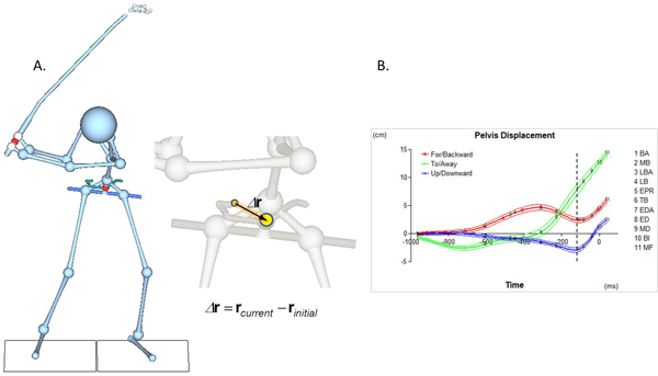
Figure 4. Pelvis COM motion during the swing relative to its initial position: posture and relative position vector at EDA (A) and relative position plot (B). At EDA (broken line in B), pelvis COM is positioned more posteriorly to its initial position (red line) due to a substantial motion toward the target (green line). EDA is also characterized by the lowest pevis COM position.
Note that 'Pelvis Displacement' is used as caption for the vertical axis in Figure 4B. Motion of a point from one position to another from one time point to another is also called displacement. Displacement is defined as 'change in position' or 'net effect of motion' and always involves two different time points. For the same point, its relative position of one time point to another is the same to its displacement.